A project network diagram is a vital concept in project management, as it is the basis of your schedule and helps you allocate resources.
If you are involved in project management, you must understand project network diagrams, their types, and their usage.
I will cover this concept in detail in today’s blog post, and I hope you won’t have any doubts about this concept after reading this post.
Let’s dive in.
Project Network Diagram
A project network diagram is an interconnection of activities that shows all project tasks, duration, logical relations, and activity interdependencies within the project.
Project network diagrams are also known as project schedule network diagrams.
A project network diagram consists of blocks, circles, lines, dotted lines, arrows, etc., and you can see relationships among activities with a quick look.
You can find the sequence of activities and verify the scope of work. It is also a good communication tool that helps you communicate your progress and issues with project stakeholders.
Project Network Diagram Terminology
The following are a few project network diagram terms.
Activity Dependency: An activity can be as a predecessor or a successor. A predecessor comes before an activity, while a successor comes after an activity.
Lead: A lead is the amount of time an activity can be advanced.
Lag: A lag is a waiting time between two tasks.
Float: Float in project management refers to time elapse or delay. This could either be a free float or a total float.
Free Float: This is the allowable time for an activity to slip without affecting its successor.
Total Float: This is the number of days an activity can be delayed without delaying the project’s finish date.
Critical Path: This is the longest path on a network and determines the project’s duration. Any delay in critical activity will affect your project duration.
How do you determine the critical path?
Simply draw the network diagram and find the longest path.
How to Draw a Project Network Diagram
The work breakdown structure ends in work packages, and work packages end in tasks or activities. To draw a network diagram, you have to go through the following steps.
- Identify Activities: First of all, you must identify all project activities. Ensure that these cover all project tasks.
- Sequence Activities: Here, you arrange the activities in order of occurrence.
- Estimate Activity Duration: This is where you find how long an activity will take to complete.
- Develop Project Schedule: This is where you develop the project network schedule diagram.
Types of Project Network Diagrams
A project schedule network diagram can be of two types:
- Activity on Arrow Diagram
- Activity on Node Diagram
Activity on Arrow Diagram
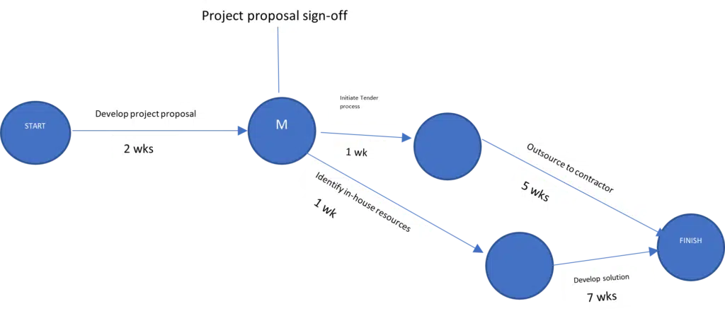
Here, activities are indicated on arrows and milestones on nodes in a circle. Since milestones are events, they have zero duration.
The diagram below shows an example of an activity diagramming network.
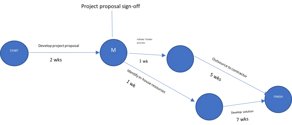
PERT (Program Evaluation and Review Technique) is an AOA schedule network diagram example.
AOA uses only finish-to-start task dependency.
Activity on Node Diagram
Activity on Node diagrams are used in developing project network diagrams and schedules. They are more common than Activity on Arrow diagrams.
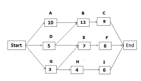
Here boxes represent activities, and arrows show the activity dependencies and relationships.
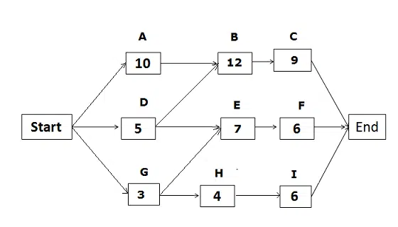
An Activity on Node diagrams is also known as a Precedence Diagram Method (PDM), and it has four types of project management dependencies.
Start-to-Start: In this relationship, activity A cannot start unless B has started. For example, pipelaying cannot start unless excavation has commenced.
Start-to-Finish: In this relationship, activity A must start before we can finish activity B. For example, normal power must be restored (start) before you can shut down (finish) the standby power.
Finish-To-Finish: In this relationship, activity A must be finished simultaneously with activity B. For example, an alkylation reaction generates a large amount of heat in petroleum refining. So, cooling water circulation can only be stopped (finish) after alkylation has stopped (finish).
Finish-to-Start: In this relationship, activity A cannot start until activity B is finished. This is the most common dependency in network diagrams.
Examples of Project Network Diagrams
Here we will discuss three types of project network diagrams:
- Program Evaluation and Review Technique (PERT)
- Critical Path Network Diagram
- Critical Chain Network Diagram
Program Evaluation and Review Technique
The US Navy developed Program Evaluation and Review Technique in 1957 to plan the schedule for the Polaris Project.
This project scheduling diagram technique helps find duration estimates when activities have uncertainties, and that is why this technique is called a probabilistic technique.
The PERT helps you develop network diagrams when you have a large one-time project with no or least historical data.
The PERT uses a three-point estimation technique to provide you with activity duration estimates.
This weighted average reduces bias and uncertainty from the estimation and improves accuracy. These estimates are:
- Most Likely Estimate
- Optimistic Estimate
- Pessimistic Estimate
The formula to calculate the PERT is as follows:
PERT Estimate = (Tp + 4Tm + To) / 6
Here:
Tm is the Most Likely Estimate. In this estimate, the chance of completing an activity is highest.
To is the Optimistic Estimate. This estimate considers the best-case scenario, so the duration estimate is the shortest here.
Tp is the Pessimistic Estimate. This is a worst-case scenario. Here, you determine the estimate considering all unfavorable conditions, so this is the longest duration the activity will take to complete.
PERT provides a better estimate by considering all possible scenarios; it is a planning tool for estimating project duration.
It is also useful in risk management, risk management planning, and Monte Carlo Analysis.
The PERT provides a duration estimate considering uncertainty or risk.
Critical Path Network Diagram
The critical path is the most common concept in project network analysis. Mr. Morgan R. Walker and James E. Kelly developed this technique in the late 1950s.
Project planners use this method to develop schedules for projects, including IT, research, and construction.
Read my post on the critical path method to understand the calculation.
Critical Chain Network Diagram
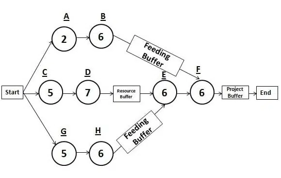
The critical path method has many drawbacks and is not useful for real projects. For example, it assumes unlimited resource availability, which is not the case for most projects.
The critical chain method addresses these concerns of resource constraints.
It eliminates most resource contention before the project starts and uses buffers for project control. It reduces change requests as the schedule is realistic and robust.
CCM is an advanced version of CPM. It includes buffers that eliminate the floats and improve behavioral change, including:
- Eliminate Parkinson’s law: Parkinson’s law says that work always expands to fill the time available for its completion. The CCM diagram has no float, so Parkinson’s law has no role here.
- Remove Student Syndrome: Student Syndrome affects the critical path when team members do not start the task until the last moment. Activity in the critical chain has no late start.
CCM uses resource-leveling to ensure optimal resource utilization. It considers resource limitations and levels resources to manage constraints.
Leveling resources sometimes increases the project duration, but the schedule is realistic, and there is a smaller chance that you will be behind schedule.
The critical chain is the longest resource-leveled path in the CCM network diagram.
Read my post on Critical Chain Method.
Uses of Project Network Diagrams
Project network diagrams have the following uses:
- Managing project schedules
- Determining project duration
- Allocating resources appropriately
- Appreciating the relationships between project activities
- Assigning buffers where necessary
Pros and Cons of Project Network Diagrams
We have discussed the project network schedule diagram; let’s now see its pros and cons.
Pros
- Shows all tasks visually
- Identifies process bottlenecks
- Helps develop the project schedule
- Shows task dependency
Cons
- Developing a project schedule diagram takes time
- For a big project, the diagram can be complex
- A minor mistake can affect the schedule
Summary
Project network diagrams are scheduling tools used by project managers to develop planning and executing projects. It lets you visualize the logical sequence of project activities and complete the project with minimal obstructions.
How does a project network diagram help you in your projects? Please share your thoughts in the comments section.
Note: This topic is important from a PMP exam point of view.

I am Mohammad Fahad Usmani, B.E. PMP, PMI-RMP. I have been blogging on project management topics since 2011. To date, thousands of professionals have passed the PMP exam using my resources.


Dear Fahad, thx for the wonderful blog and knowledge yoou shared with us. It has definitely helped me a lot. Can u please explain that how we can reflect various relationships like Start to start, Finish to Start etc through Activity on Arrow network (AOA)